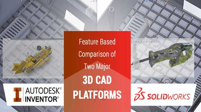
Software battle between SolidWorks Vs Inventor: Which one is the best?
There are two 3D computer-aided design (CAD) programs available for the design of machine parts: Solid-Works and Inventor. They both offer more than just modeling tools, including simulation, & rendering.
The softwares are both used in industry, so either one is a good choice. There tends to be a difference in what features you want. The choice of Inventor is usually appropriate if automating the design process is a priority. However, Solid-Works' design workflow is more convenient if you are creating a machine from scratch.
The best career strategy is to find out which one is preferred by companies for which you aspire to work and learn that one first. There are almost no differences between these two tools, so it's hard to pick which one is better, but I would recommend solid works since it gives you access to the previous version, which makes it easier for you to integrate the software, whether you're a novice or a pro.
Key differences between Inventor & Solid-works
Assemblies
In contrast to Solid-Works, Inventor produces assemblies by using joints, constraints, and parameters. This is essential because you will need to define joints later on to simulate stress. Thanks to the assembly building process in Inventor, these are already set.
Inventor's Assembly environment makes it easy to preview the movement of assembly components, and it provides greater flexibility than Solid-Works' Animation environment set.
Collaborative Work
Sharing a view with others is possible with Shared View Collaboration in Inventor. This view is entirely visual: It only shows you the model, which doesn't move, has parameters, etc. Still, this feature makes it possible for others to view the model, which can be useful for checking the progress of a design or showing clients ideas.
Scripting
The emphasis during the design process is much greater in Inventor than in Solid-Works due to its scripting capabilities. You can program parameters instead of visually modeling a set of standard parts used in your company, for example, if you want to create a set of standard parts, but not have to open them every time you need one.
After you have modeled a part in this way, you can save it as a plug-in so that in the future, all you need to provide is the diameter and length, for example; the other factors are calculated for you. Scripting, therefore, allows you to avoid modeling each part individually. You can automate the rest if they're similar.
Simulation
It's more instinctual to work with simulations since Inventor was created and relies so heavily on scripts. For instance, when performing simulations, it converts constraints into mechanical joints automatically. It can work with accelerations and contact friction, which is an essential part of every joint's simulation. It even allows you to do explicit simulations.
Solidworks
Old-based Modeling
An important part of why Solid-Works is so powerful is its old-style modeling. Feature Manager will show the operation when you extrude a cut, for example. After that, if need be, you can go back and add more features to the previous cut, and go forwards again, re-enabling the cut. If you need to add details to a project during the conception stage without going back and undoing the process, this feature is useful.
Configurations
Feature Manager Design Tree's Configurations tab is a very powerful and important part of Solid-Works. A system for configuring the same part or assembly in multiple ways, as the name implies.
Instead of creating two separate parts, you create two configurations within the same part if you want a bar with and without drill holes. Solid-Works has history-based operations, which allow suppression.
The use of parametric modeling equations or by suppressing features in a specific configuration, the program lets you construct these configurations inside the same model. Remember, this can make designs extremely heavy, which might cause the program to lag or become buggy.
Improvement in Mouse Movement
To maximize efficiency while working, you can customize the right-click mouse movements in Solid-Works. When you often use the Mates tool, instead of searching for it each time, you can enable it whenever you right-click and slide to the left.
To get online demonstration, watch the following video tutorial.
Video Source: DISE?O MEC?NICO PARA TI
Multi-solid Modeling
If you're going to design two parts that will interact with each other, you must model each separately, and then you will join them together in an assembly.
In any case, let's say that the parts never move relative to one another and that they share a geometry - the geometry of perforations, for instance. That being the case, modeling them as separate solids is much easier in that case.
Solid-Works can be used for this purpose. It is possible to choose whether to apply features to one or both solids when applying features to a part. Additionally, a part file can contain more than two solids.
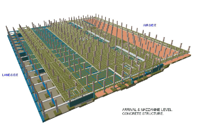
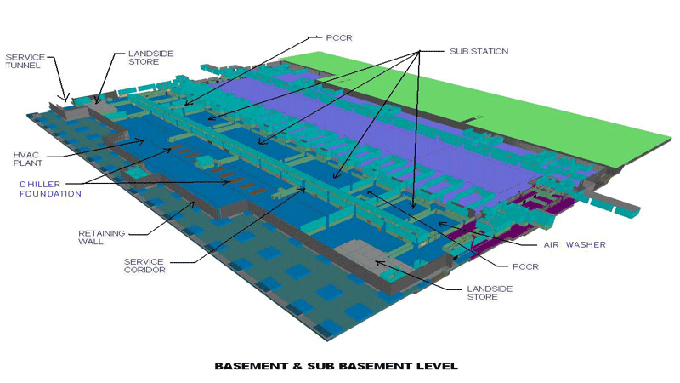
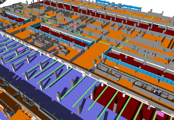
Gallery
Feel free to contact us for BIM requirements. One of our representative will respond you within 24 Hours. Send us your projects requirement today and grow your project.
Explore More !