Download Ladderes Revit Families BIM Objects
The Revit families refer to the group of design elements, along with a common set of properties that are known as the design parameters. The design elements that are organised into the Revit families are doors, walls, structural members, mechanical equipments or annotation design elements, for example, door tags, elevation symbols and column gridlines.
The Revit families have been categorised into three categories, which are loadable families, system families, and in-place families. These Revit families can be created and modified outside the project environment, and they can also be loaded into any design project.
Discuss the steps of creating the heroic ladder family in the Revit software
The heroic families have been used in high-level design work environments. To create the heroic ladder family in the Revit software, several steps need to be followed, which are as follows:
Creating a regular parametric ladder
The Revit software is another powerful tool which offers revolutionised architectural design and construction workflows. The comprehensive tool sets of the Revit software have been tailored for the architects, civil engineers, contractors and other project stakeholders that has been involved in the building project. The feature-rich interface of the Revit software helps to empower design professionals with an array of tools that have been designed to facilitate efficient design, analysis, documentation, and collaboration throughout the lifecycle of the project.
Creating a regular parametric ladder
At the first step of creating a heroic ladder family in the Revit software, the user has to create a normal parametric ladder. In this stage, the user does not have to worry about the angles of the ladders. This stage helps to provide a basic understanding of the reference planes, labels, dimensions and extrusions. The rails of the ladders have been modelled with simple extrusions.
Creating a nested family
In the next step, the user has to create a nested family that contains a single rung. After that, the user has to load this nested family into the main ladder family and has to place the family at a distance from the bottom of the ladder.
Creating an array for rungs
After creating the nested family, the user can use arrays. In this context, the user can find the tool in the modify tab, and it needs to be ensured that the Move to: Last option should be used. The design element should be placed at the top, and it should be aligned with the reference planes. In the next step, the user has to select one design element in the array and has to select
Assigning the array formula
In the case of automatically adjusting the number of rungs, the user must add a formula, and it has been done on the basis of the height.
Making the family work plane-based and uncheck
In this stage, the user has to nest the entire ladder in another family, in which the user are able to control the angle. In this context, the user has to make adjustments. The user can see two parameters, including Work Plane-Based and Always vertical, in which the Work Plane-Based box should be checked and the Always vertical box should be unchecked. This process helps to host this family on a reference line.
Creating a new family and adding a reference plan
While creating a new family, the user can create the reference planes, dimensions and labels in the left elevation.
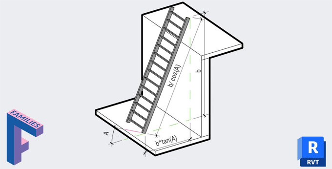
Creating a reference line and adding an angle label
While the user wants to add an angle in the Revit family, the user has to think about the reference line. In this context, the reference line should be created at the bottom left corner in the elevation view, aligning the end point of the reference line to the reference planes, and an angle label should be added to the reference plane. The user also has to adjust the angle dimensions as it will rotate around the intersection of the reference planes.
Placing the nested ladder family on the Reference Line Work Plane
In this stage, the user has to ensure that the nested ladder is loaded into this family. Next, the user has to go to the 3D view, use the view cube to set the view of the family at the corner, and has to place the ladder. While creating the ladder, the user has to select the Place on Work Plane option, select Pick… in the Placement Plane dropdown menu from the option bar, and has to select the Pick a plane option. The user is allowed to pick 4 different work planes in the Revit software, one at each extremity and two along the length of the line.
To get online demonstration, watch the following video tutorial.
Video Source: BIM Pure
Aligning and locking the ladder
In the next step, the user has to go to the left elevation view, aligning and locking the ladder to the end point of the reference line.
Download Ladder Revit Family
Assigning the height of the ladder
In the next step, the user has to assign the actual height of the ladder.
Adding other parameters and testing the family
The user can add other parameters from the nested ladder, for example, the width of the ladder, the rung dimensions and others. In the case of adding any missing reference planes, the user has to load the family into a project and has to test it.
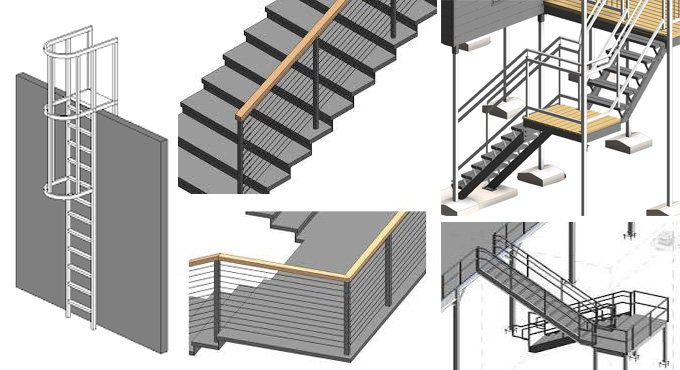
Gallery
Feel free to contact us for BIM requirements. One of our representative will respond you within 24 Hours. Send us your projects requirement today and grow your project.
Explore More !