How to Create a Floor Plan in Revit
Floor Plan generator tool for Revit Software
The floor plan generator is one of the most effective tools for the Autodesk Revit software, which helps to demonstrate the creation of floor plans in the Autodesk Revit software. The Revit software helps to streamline the design process, create interior designs, is involved in facility management and also helps to improve the design outcomes in real estate development. The Revit software also helps to demonstrate the possible solutions for the permutations, thus enabling the users to explore and optimise the design alternatives more efficiently within a short time.
To get started with the creation of the floor plan, the user has to open the Revit software and then select a new project or template. On the other hand, the Revit software has also been used to draft a design layout quickly to create the floor plan.
What are the key functionalities of the Revit software for creating a floor plan?
The Revit software offers numerous functionalities to create an accurate 3D plan, which are as follows:
1. The Revit software helps to add pre-made floor plans.
2. The Revit software helps to place and adjust the positions of the doors, windows, and water supply on the design of the floor plan.
3. With the help of the Revit software, the users can input the floor settings.
4. The design features of the Revit software help to convert the shape lines into walls based on input parameters.
5. With the help of the Revit software, the users are able to view and select the generated floor plans.
6. The 2D floor plans can be transformed into 3D building models by using the Revit software.
Key requirements to create a Revit floor plan
To create a 3D floor plan, the key requirements are:
1. Windows® 10 (64-bit edition)
2. Autodesk Revit 2024
Discuss the process of creating a floor plan in Revit software
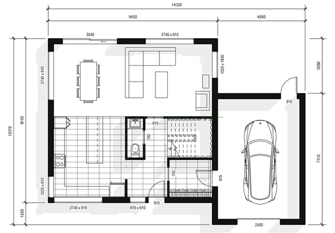
Users can create a residential floor plan in the Revit software by using the following steps:
Setting up the height of the levels
At the beginning of the floor plan creation, the user has to assign the walls to specific heights. In this context, the user has to go to the elevation view to make sure that all the required levels of the wall have been created, and they have to set them to the correct height.
Placement of the wall intersection at the internal origin
The user has to use the shortcut VG to go to the Visibility/Graphics menu within the Revit software, and then the user has to scroll down to search for the Site submenu. After that, the user has to check the Internal Origin box, which helps to create walls at the intersection of the origin.
Creating a design layout with detail lines
Within the Revit software, the user can create a design layout by using detail lines. In this context, the lines are visible only in a single view. The user has to use the coloured lines to distinguish them from the design model elements.
Using shortcuts Cs
The user can select an element and use the shortcut Cs to create a similar element, which helps to create walls more quickly.
Using temporary dimensions
While selecting an element, the user can also see a dimension in blue, which is called the temporary dimension. In this context, the user has to drag the dots to adjust the witness lines. The user can also change the value of the blue text to adjust the dimensions.
Using the trim tool to adjust the walls
The trim tool of the Revit software has been used to trim or extend the design elements to be joined together. By using the trim tool, the users are able to complete the design layout.
Adding doors and windows
After completing the wall design layout, the users are able to add doors and windows in the layout. In this case, several shortcuts can be used to save design time; for example, DR is used to add doors, WN is used to add windows, WA shortcut is used to add walls, and Spacebar has been used to flip the walls, doors and windows orientation.
Adding design components and lines
To add the design components and lines, the user can use the Create Similar tool to add a toilet, fridge, wardrobe rod, and other components. The model lines can also be used to complement the families in the design.
Using overlays
To get the second floor view, the user has to activate the Underlay and set the Base Level to Level 1.
Using reference planes to align the design components
The user can also use the reference planes, which help to reference the position on multiple levels.
Modelling a thin floor
To get a ceramic floor pattern, the user has to create a new floor using a thin type.
Annotate the drawing
The user can use the template that includes tags for doors and windows.
Creating a dark wall poche
In the next step, the user can also use the Visibility/Graphics menu to add a dark wall poche in the design, thus creating a good presentation effect in the floor plan.
Printing the design
After making all the final touch-ups, the user has to place the view on a sheet. They can adjust the crop region of the view around the house, can also adjust the sheet information, and after making all these adjustments, the floor plan is ready to print.
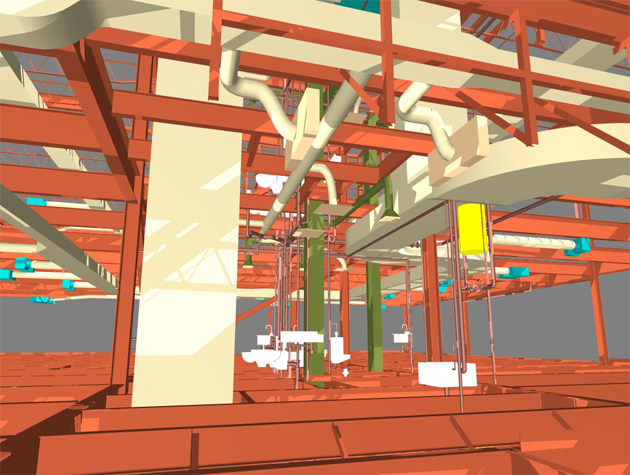
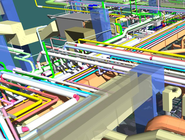
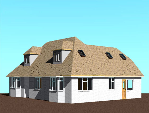
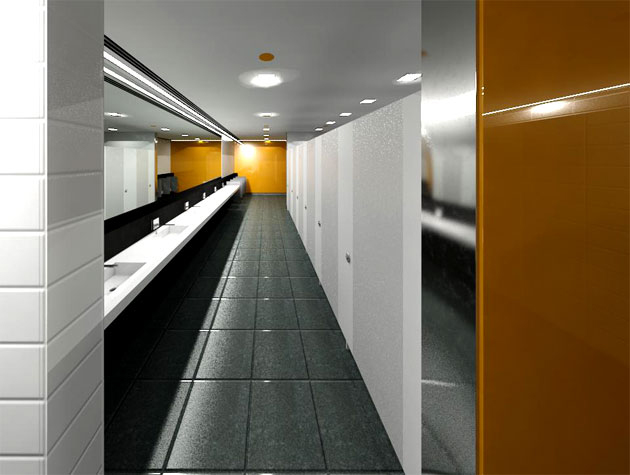
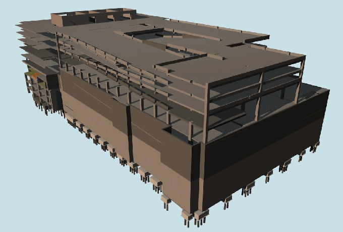
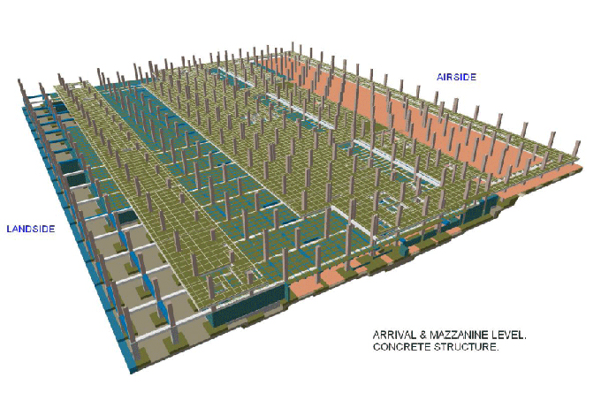
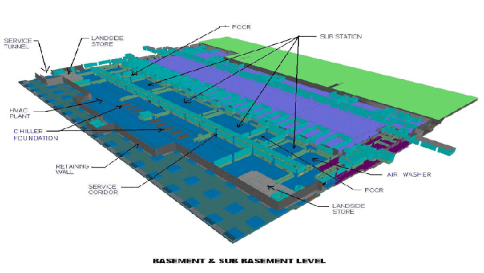
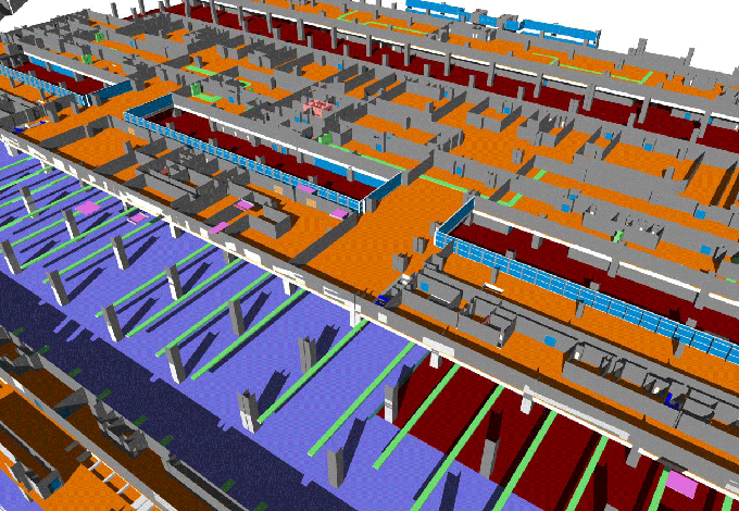
Gallery
Feel free to contact us for BIM requirements. One of our representative will respond you within 24 Hours. Send us your projects requirement today and grow your project.
Explore More !