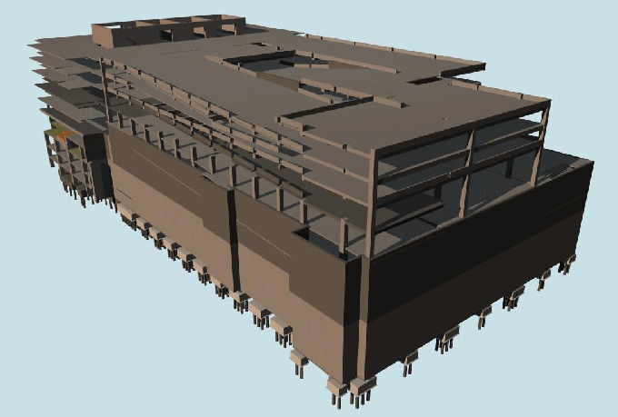
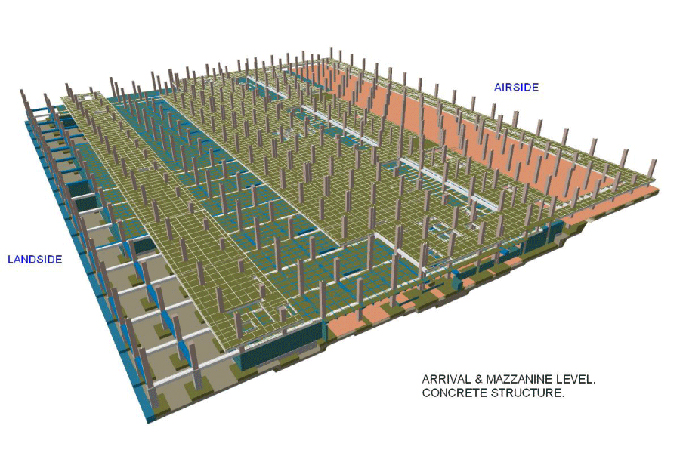
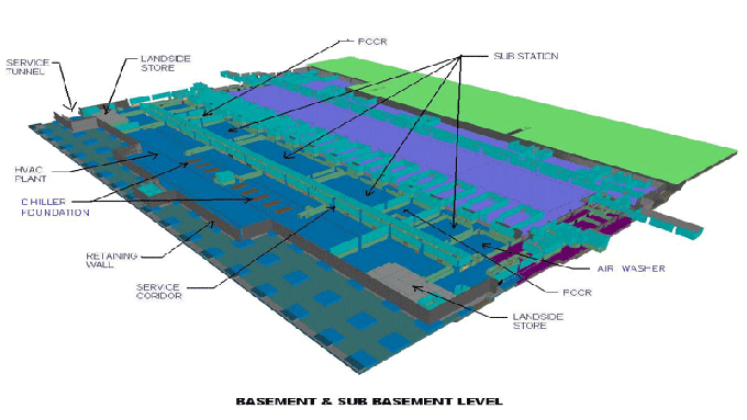
How to get 3D BIM view in Revit 2026?
The Revit 2026 software version has been developed to combine installations, architecture, structures, and the construction process. The Revit 2026 software offers new optimisation and improvement features, which help to meet the design demands of large and complex design models. The Revit 2026 software enables design professionals to create more precise design models, which helps to connect the design and manufacturing process.
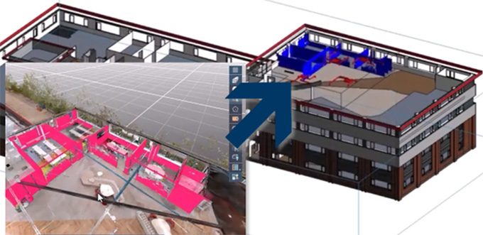
The global parameters of the Revit software allows the users to encode and capture the design intentions in a design model, which enables the users to define the relationship between the design elements. Thus, the design parameters are able to handle the design dimensions and values throughout the entire design project.
The Revit 2026 software version helps to raise the communication between the users, which enables them to share their design thoughts and information, thus helping to achieve more effective design outputs.
Learn about the conversion of 2D CAD drawings
The CAD to Revit conversion refers to the process of transforming the 2D CAD drawings into the 3D design models within the Revit software. While the user imports the DWG file into the Revit software, 2D lines appear as a reference overlay. The CAD conversion process also helps to transform the flat lines into the parametric Revit elements, for example, creating walls with material properties, windows with thermal values, doors with clearance data, structural elements with load-bearing classifications, or MEP components with flow attributes. These smart design objects help to support coordination, energy analysis process, clash detection process, and also construction documentation process in ways that the 2D CAD drawings can not.
Understanding the benefits of converting 2D CAD drawings
Increasing design collaboration
The converted CAD drawings act as the centralised hub for all project stakeholders. This integrated environment of the converted CAD drawings allows the users to detect clashes at an early stage of the project. Thus, the converted drawings help to save the overall design time, money and materials on-site.
Improved clash detection process
The converted 3D design models help to resolve the conflict between the architectural, structural, and MEP systems by detecting the clashes at the beginning stage of the design project.
Better visualisation
The converted CAD drawings have been used to generate more photorealistic renderings and detailed 3D views of the design objects from any angle. This visualisation feature enables the users to better understand the design intent more easily, which helps to provide meaningful feedback on the design model, thus allowing the users to make more informed decisions regarding the design process at the earliest possible time.
Accurate cost estimation
While converting the 2D designs into the 3D BIM model, the design objects have been created along with deign properties like design dimensions and materials. This feature allows the automatic extraction of quantity take-offs, thus the project stakeholders can generate accurate bills of materials for the design project.
Improving project accuracy and reducing rework
The converted CAD drawings help to ensure design consistency, as well as, it helps to eliminate human errors in the drawings, thus helping to reduce the costly on-site rework.
Learn about the process of converting 2D CAD drawings
CAD cleanup process
At first, the user opens the DWG file in the AutoCAD software, and they have to resolve the inconsistencies in units, scales, layers and redundant elements. In addition, the user has to also remove the unused blocks from the designs and has to ensure that the layer naming follows a logical structure.
Import process
In the next step, the user has to link or import the cleaned CAD files into the Revit software, which helps to align them to the correct level and also helps to coordinate the design origin. It also needs to be verified that the unit scaling will match between the CAD file and the Revit project.
Tracing the manual elements
The user can also trace over the CAD geometry, which helps to create native Revit design elements, for example, inserting the doors and windows at the marked openings, placing the walls along with the CAD lines or drawing the MEP routes over the single-line diagrams.
Assigning design parameters
In the next step, the user has to assign the type parameters, design materials, classification codes and the performance data to the Revit design elements. This process helps to transform the raw design geometry into the BIM-ready design objects, which helps to support the design coordination process, design analysis process and design documentation process.
Validation
In the next step, the user has to check the converted model to maintain the design accuracy against the original CAD drawings. The users also have to verify the design dimensions, the classification of the design elements, and the code compliance of the designs. In this case, any kind of discrepancy needs to be resolved before issuing the design output.
Gallery
Feel free to contact us for BIM requirements. One of our representative will respond you within 24 Hours. Send us your projects requirement today and grow your project.
Explore More !