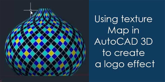
How to apply texture Map in AutoCAD to generate a perfect logo effect

AutoCAD contains a huge library of materials which can be applied in rendering process. But, it is possible to produce your own custom materials in AutoCAD by including some particular properties. The materials which are formed can contain various characteristics like surface texture, glossiness, transparency or even luminosity.
In this article, JAIPRAKASH PANDEY, the renowned corporate cad trainer, shows how to create a custom material containing a texture map in AutoCAD as well as use it on 3D solid objects for producing an effect of imprinted logo. A cuboid and a sphere with see-through AutoCAD logo is used in the tutorial.
Material with texture map: In order to open materials browser palette, type MAT on the command box. Otherwise, just click on the Materials Browser icon available on Materials panel in Visualize tab in the 3D modeling workspace of AutoCAD.
Choose the default Global material from the palette and then right click and opt for duplicate out of the contextual menu. Double-click on the material that is produced and assign a name in materials editor palette. In this tutorial, it is titled as Logo Material.
Extend the generic tab and click on the image box, choose the image to be applied for the logo and click on Open button.
Here, AutoCAD logo having transparent background is used that is in PNG format.
In order to open the Texture Editor Palette, click twice on image box. Extend the Scale tab and modify the size in Horizontal and Vertical scale as per the size of the logo to be visible on the object. In this tutorial, a scale of 5 units for both directions is selected.
Ensure that none is highlighted in the Horizontal and Vertical drop-down menu of Repeat tab. Once the custom Logo material is produced, close Material editor palette.
How to use the material to object: To use the Logo material that is already created, just drag and drop it with the mouse from materials browser to the object in the drawing area. Ensure that visual style is chosen as realistic to observe the real-time effect of the material on the objects.
In the first illustration, the logo seems to be deformed, but it can be perfectly aligned with material mapping feature. Now, start with cuboid.

Click on Box option available in Material Mapping Flyout of Materials panel on Visualize tab then opt for the cuboid from drawing area and press enter. Various arrow type grips in diverse directions along the box will be visible. Click on the grips and drag them in relevant direction for arranging the logo perfectly.
As soon as the object is arranged perfectly, further press enter to quit material mapping command. The process is also applicable for a spherical object. It is not compulsory to apply spherical material mapping option for spherical and other related geometries.
It is possible to generate various effects by selecting heterogeneous material mapping options on geometries. In this tutorial, box material mapping option is applied on a spherical object.
Article Source : www.thesourcecad.com
